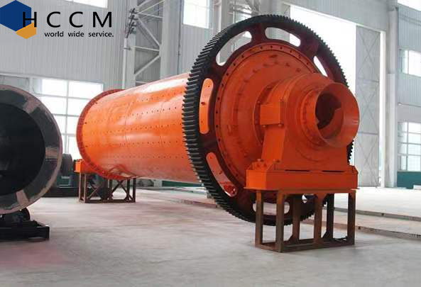
Ball mill ball grinding mill grinding machine
Ball mill ball grinding mill grinding machine
Description of tank production process
1. Blanking cylinder plate:
A). Determine the sheet thickness and width according to the diagram and line diagram. Lengths and dimensions need to be right, and the diagonals are of equal length.
b) Set the required length when setting according to the desired length of the rolling machine. When rolling, it is necessary to draw a cut line and a drill point at the cut point to brush.
C). Check drawing according to size and requirements. Fix the cutter, and leave 5mm on the side of the carved dimension as a boundary plan allowance when planning.
D). The curve should be straight and the slag should be cleaned thoroughly. After passing the inspection, it will be transferred to another section.
2. Cylinder placement:
A). Check the size of the sheet according to the drawing, and when it is correct, get in the car.
b) Align the parallel and vertical between the plate and the machine tool, depending on the line drawn by the assembler on the plate.
C). Press the workpiece press requirements before planning.
D). It should first be straight, and then beveled (according to the requirements of the picture).
e) After plotting on one side, turn and make sure the piece is parallel and straight to the final face.
f). First a straight plane, then a bevel. Make sure the width matches the drawing requirements, error should be less than 1mm, groove position is correct, plus and minus are correct.
g). After passing the inspection, transfer to another section.
3. Roll the cylinder:
A). After planning, check the sheet size, and continue to draw the line: Fix the cut line “backwards” in the rolling process, after confirming that the length, width and vertical are correct, draw the line at a distance. Check the 100mm point from each side of the four corners, check the position of the four points, print the good points, think of several examples after they are correct, and make an eye catcher. Only when there is no error can the circle come to work.
b) The position of the large drain planned on the plate should be in the outer ring. The length of the sheet metal should be perpendicular to the direction of rotation of the rolling machine.
C). For indenters, use a template 1/6 of the diameter of the inner diameter and the circumference of the corresponding cylinder to check the accuracy of the radian, and gradually get the match.
D). Bumps on both sides will be rounded after the round.
e) Cut off the extra steel sheets on both sides and “return to the circle” after welding. Check the circumference with the sample plate, and check the inner diameter with a steel ruler.
f). Once passed, move on to the next section.
4. Butt joint and cylinder weld:
A). Check the barrel section (circumference and length) after rolling. Number each part according to the organizational position of the cylinder diagram, and connect in chronological order of cylinder diagrams. The axial welding position of the two adjacent parts of the cylinder should be stunned by 1800, which should be measured accurately with a steel roller on the outer ring.
b) Check the straightness of the cylinder and parallelism of the flange after docking, check the length of the flange and cylinder body, check the engine clearance, and check the total length.
C). The supporting support angle of the flange should be perpendicular to the flange.
D). After connecting the butt of the cylinder body, use the manual connection to align it. Manual welding should be thoroughly cleaned of slag.
e) Perimeter and axial welds on the outside of the cylinder are welded by automatic welding. Axial welds should be bevel when rotating and cutting, and unwanted grooves should be strong during welding.
f). After the outer coil seam and axial welding are completed by automatic welding, carbon arc planing is applied to the cylinder to plan the groove release, and carbon dioxide is applied to the welding seam in the cylinder. The body of the cylinder needs to be drilled and the welding is completed. The outer welding seam is above 1-3mm, the inner welding seam is above 0-1mm, and the upper part of the inner welding seam should be smooth. Welding should be flawless such as pitting, slag inclusion, and leakage welds affecting the force.
5. Fault detection of welding sim and aging treatment of cylinder:
A). The welding seam of the cylinder body should be strictly inspected. If there are errors such as weld holes, loose welds, slag inclusions, etc., make a clear mark on the defect of the welding sim and record it, and finally plan and repair. The number of maintenance connections on the same fault is not more than twice.
|
Model
|
The chamber
speed(r/min) |
Ball
Load (t) |
Feed In
Size (mm) |
Feed Out
Size (mm) |
Capacity
(t/h) |
Motor Power (kw)
|
Weight (t)
|
|
900 ×1800
|
38
|
1.5
|
≤ 20
|
0.075-0.89
|
0.65-2
|
18.5
|
3.6
|
|
900 ×3000
|
38
|
2.6
|
≤ 20
|
0.075-0.89
|
1.1-3.5
|
22
|
4.6
|
|
1200 ×2400
|
35
|
3.5
|
≤ 25
|
0.075-0.6
|
1.5-4.8
|
37
|
11
|
|
1200 ×3000
|
35
|
5
|
≤ 25
|
0.075-0.4
|
1.6-5
|
45
|
13.8
|
|
1200 ×4500
|
35
|
7.5
|
≤ 25
|
0.075-0.4
|
1.6-5.8
|
55
|
14
|
|
1500 ×3000
|
27
|
8
|
≤ 25
|
0.075-0.4
|
2-5
|
75
|
15
|
|
1500 ×4500
|
27
|
12
|
≤ 25
|
0.075-0.4
|
3-6
|
95
|
18
|
|
1500 ×5700
|
27
|
15
|
≤ 25
|
0.075-0.4
|
3.5-6
|
130
|
21.7
|
|
1830 ×3000
|
24
|
12
|
≤ 25
|
0.075-0.4
|
4-10
|
185
|
28
|
|
1830 ×6400
|
24
|
23
|
≤ 25
|
0.075-0.4
|
6.5-15
|
210
|
34
|
|
1830 ×7000
|
24
|
25
|
≤ 25
|
0.075-0.4
|
7.5-17
|
245
|
36
|
|
2100 ×6500
|
21
|
31
|
≤ 25
|
0.075-0.4
|
14-26
|
355
|
52.8
|
|
2200 ×7000
|
21
|
37.6
|
≤ 25
|
0.075-0.4
|
15-28
|
400
|
56
|
|
2700 ×7000
|
18
|
61.8
|
≤ 25
|
0.075-0.4
|
18-35
|
710
|
73
|
<<Previous:200tph Hot Mix Asphalt Plant Stationary Asphalt Mixing Plant
- Product List
- Concrete batching plant
- dry mortar plant
- asphalt mixing plant
- block making machine
- concrete mixer and pump
- self-loading concrete mixer truck
- cement silo
- concrete mixer truck
- concrete boom pump
- Crusher plant
- Other hot products
- Stationary Eco-Friendly Concrete Brick Machine Block Machine Manufacturer
- Professional Mini Excavator Manufacturer Small & Compact Excavators
- Hydraulic Block Making Machine, Vibration Press Brick Machine
- Wall Putty Ceramic Tile Adhesive Machine Dry Mortar Machines Ceramic Tile Adhesive Making Machine
- Customized Automatic Concrete Hollow Block Molding Machine
- Concrete Batching Mixer Vertical Shaft Planetary Concrete Mixer With Lift
- Customized Three Bins Concrete Batching Plant
- 50M3/H Stationary Planetary Concrete Batching Plant
- 4cbm Self Loading Concrete Mixer Truck for Self Mobile Concrete Mixer
- Factory Directly JS500 JS750 JS1000 Forced Double Shaft Concrete Mixers